How to build a low cost 26" Python Lowracer:
On this side I try to explain the building of a low cost version of the Python. It is similar to the prototype P3 which you can see on various pictures and which I have in service for two and a half year now (28.09.2006) and which has reliably carried me for over 18.000 km.
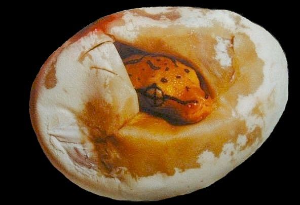
1. Inseam Length
Measure the inseam length of your legs (barefoot). You need a large format hard cover book. Stand straight up, with your back against the wall. Place the book between your legs as shown in the illustration. Make sure the the book is rectangular against the wall. Use your hands to pull upward on the book to simulate saddle pressure. When the appropriate pressure is reached, hold the book in position. Make sure the book is square with the wall! This may require some help from your assistant. When the book is in the proper position, your assistant should measure from the floor to the top of the book as illustrated, and write it down. Perform the entire procedure at least two more times until you get a fairly consistent measurement. Average your three consistent measurements.
The inseam lenght decides if you can use 28" or 26" wheels or have to switch to even smaller front wheels. In this text I presume an inseam of 86 cm. Together with standard 170 mm cranks you can use a 26" front wheel with 44-559 tires.
The presumed body height is 179 cm. With the appropriate seat angle and two 26" wheels, the wheelbase will be 129 cm.
2. Material
To build the Python you need some bike parts and rectangular tubing of construction steel. Important tools for the work are hacksaw, drill and welding machine (I used a MAG).
The 26" rear wheel will become the Python's front wheel (FW). Be sure that the FW is perfectly trued and has the same tires as you want to use later.
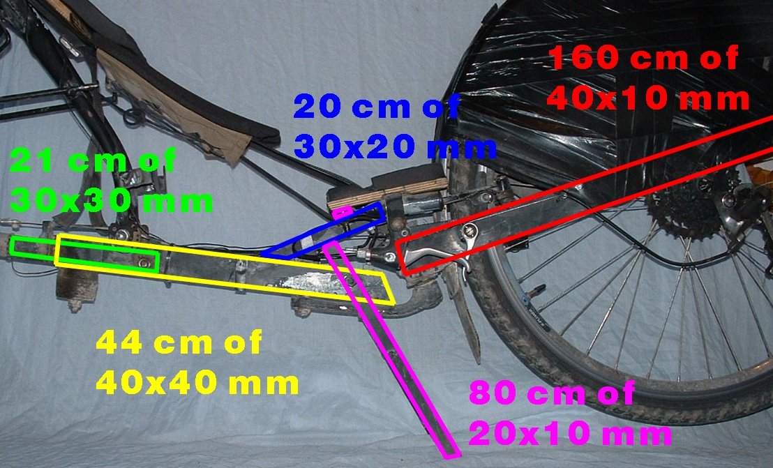
Overview of the rectangular tubing sizes that I used (wall thickness 1.5 mm):
Weight (kg/m) of rectangular mild steel tubing (St 37-2, S235JR, DIN 2395):
| Size [mm] |
x 1.0 mm |
x 1.5 mm |
| 20 x 10 |
0.433 |
0.632 |
| 30 x 10 |
0.576 |
0.868 |
| 30 x 20 |
0.751 |
1.107 |
| 30 x 30 |
0.733 |
1.340 |
| 35 x 35 |
1.047 |
1.578 |
| 40 x 10 |
0.733 |
1.107 |
| 40 x 40 |
1.204 |
1.813 |
The Python frame consists of 5 units. The front, middle and rear part, the stand and the seat. Each part can be built separately.
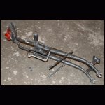
3. Front Part:
- 26" rear wheel with sprockets and 44-559 tires (FW)
- one bottom bracket (BB) (cut out from donor bike) with shell and crankset
- one set of rear dropouts (cut out from donor bike)
- one set of cantilever pivots (cut out from donor bike) and a v-brake
- chain, derailers and shifters
- one wide 26" rear fender
- one cartridge BB with shell for the steering pivot (SBB) (cut out from donor bike)
- one alloy crank
- two pieces à 85 cm of 40x10x1.5 rectangular tubing
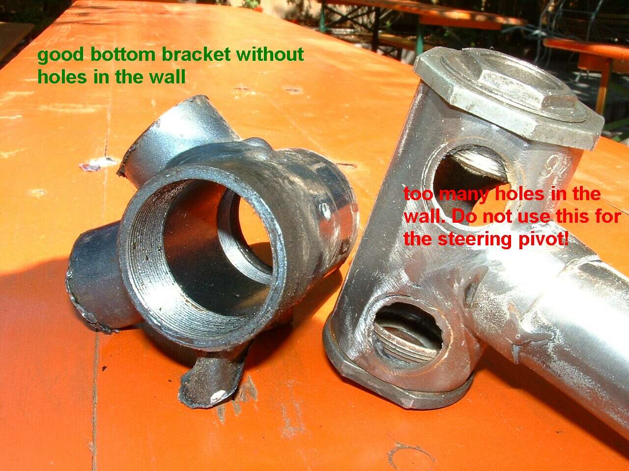
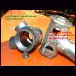
The bottom bracket shell for the steering pivot (SBB) should have as less holes as possible. If there are big holes for the seat and down tube as well as for the chain stays don't use it. However you may use it for the Python´s real BB.
3a.
Clean the SBB shell from all remainings of stays and varnish. Screw two cups into both ends, to protect the threads from damage and the shell from warping.
3b.
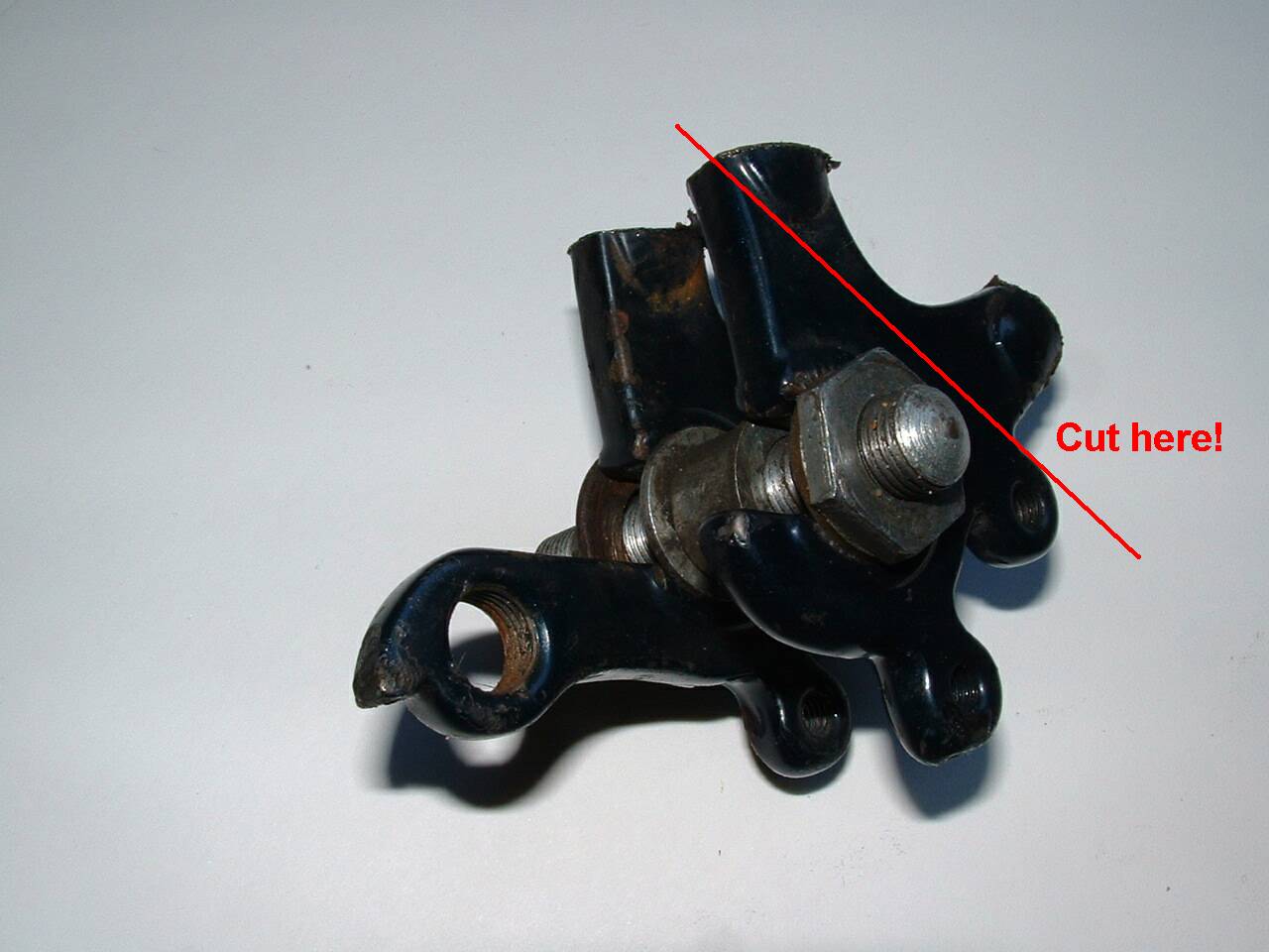
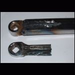
Prepare the dropouts as shown in the picture below. Primary goal is to make the angle between cutting line and dropout as big as possible, and secondary to minimize the distance between center of dropout and the cutting line (but always leave enough space for the axle nuts or quick release). Cut the dropouts and grind them so that they can stand on a plane surface, both on the same level. For better alignment you can screw both dropouts onto an axle like shown in the picture. Remove the varnish from the intended welding areas. At last fasten both dropouts to the FW axle in their normal position and align them.
3c.
Set up on edge both 40x10 tubes between two tables of the same height and make sure that they are parallel. Place the FW with the dropouts onto the upper edge of the tubes. The FW axle should be about 43 cm from the SBB edge of the tubes (in fact I mean the point where the perpendicular from the FW axle intersects with the rectangular tube, furtheron called the FWaP). This edge will be referred as the "rear end". Adjust everything, so that the FW is completely centered between the parallel tubes. The inner edge of the dropouts should be in line with the inner edge of the tubes.
Now weld the dropouts onto the tubes and have a cup of coffee.
3d.
Temporary fix the front end of the tubes by tack welding a rod between them.
Make vertical incisions in the inner walls of the tubes 10 cm behind the FWaP and bend both rear ends inwards so that they almost touch the tire. There should be left 10 mm of clearance between the flanks of the tire and the inner tube walls. Tack weld this position. Now place the SBB in the horizontal and vertical middle. The center is 38 cm from the FWaP. You may tilt the upper side of the BB shell some degrees to the rear so that it will be easier to achieve a steering angle of 65 to 68 degrees without having too much BB height. Assure that the SBB is exactly in line with the FW (pushing a long rod through the SBB helps with the alignment) and tack weld it to the tubes. Then bend and weld the overlaying ends of the tubes around the shell. Finally weld a rectangular sized plate between the insides of the tubes. This plate is for stiffening and for mounting the fender (the plate should have a 5 mm hole for this). Leave about 2 cm of clearance between the plate and the tire.
In general, e.g. if you use other wheel sizes, always keep the distance between steering pivot and FWaP as short as possible. On the other hand make the distance beween BB and FWaP as long as you can. This increases the chain length but it is better for the drivetrain and gear shifting and avoids any heel/rear derailer collision.
3e.
Clean the BB shell like in 3a and assemble the whole BB with cranks and chainwheel. It is a good idea to mount both cranks parallel. This makes the measuring and alignment with the FW easier.
3f.
Make an incision in the inner wall of the right 40x10 tube, 17.2 cm from the FWaP. Make a second incision 10 cm from the FWaP in the left tube. Remove the fixing rod. Bend both ends inwards until there is only 8 mm space left between the tire and the tubes. Tack weld both ends together. Connect the two ends with two triangular 1.5 mm thick plates and one rectangular sized plate. Leave 2 cm of space between the plate and the tire.
3g.
Now vertically cut the connected ends 42 cm from the FWaP. The resulting vertical plane will go right through the center of the BB. Draw the half circle shape of the BB shell on the outer sides of the tubes and cut them out. Now place the whole BB assembly into that excavation. Align them with the FW and tack weld it.
A good way to align the BB exactly perpendicular with the FW is pushing a rod through both crank pedal holes, marking the center point of the rod and turning the cranks into their highest and lowest position until the rod touches the tire. In both positions the center marking should be in line with the the middle of the tire surface.
The given 42 cm distance between BB and FWaP is for riders with 86 cm inseam. Theoretically you can go down to 34 cm, which corresponds to 78 cm inseam. But this will lead to problems with the drivetrain and to collision of right heel and rear derailer (unless you have a Rohloff 14 gears SpeedHub). The absolute minimum distance for a 26" FW, I would recommend is 40 cm (84 cm inseam). No problems are expected for longer legs.
3h.
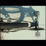
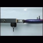
Now that the BB is in place, it is a good idea to assemble and test the whole drivetrain. First mount the rear derailer, then the shifter and the cable. It is special for the Python design that both shifters are attached to the front part of the frame (which combines the functionality of BB, chain stays, fork, steering head and handlebars). Thus making the front part independant and detachable from the rest of the frame without any cable hassle. I simply weld both shifters to the tube, 9 cm ahead of the SBB.
When the rear derailer is working you can mount the chain and check the chainline and the gears. If you have some patience left you can also weld the front derailer tube in place and adjust the chainwheel gearing.
3i.
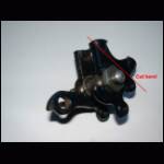
Now is a good moment to put the brake sockets in their place. Due to little space around the steering pivot, v-brakes are a good choice. It is best to weld the sockets on the underside of the 40x20 tubing. For simple alignment I mount both pads, preload the socket spring and press the pad to the rim as if braking. Then I tack weld the pivot to the tubing and check the alignment. The tack welding allows for further adjusting before the final welding. This procedure can be done independantly for both brake arms.
4. Rear Part:
- 26" front wheel with 44-559 tires
- one unsuspended 1" MTB front fork with brakes and fender
- one 37 mm long piece of seat stay
- 20 cm of 30x30x1.5 rectangular tubing
- two plates 70x30x2 mm of steel
- two plates 70x40x1 mm of brass
4a.
For the rear frame just weld a 30x30 tubing onto the head tube. Be absolutely sure that the tubing is vertically in line with the wheel. Make some incisions to connect the round and the rectangular tubing properly. For the rear suspension drill a horizontal and a vertical hole through the connected tubes. Distance between both holes is about 9 cm (if you are heavier than 80 kg choose 10-11 cm). The vertical hole is 11 cm from the rear end of the head tube. Reinforce the horizontal hole with a small tube, e.g. from a seat stay. It should be big enough to push through a rear axle. A front axle will later be pushed through the vertical hole.
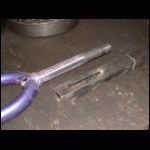
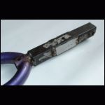
4b.
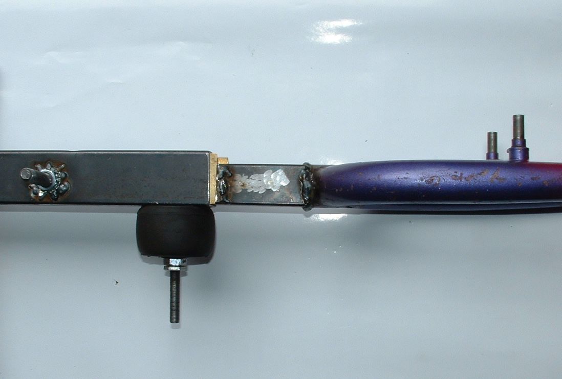
Now prepare the four plates of steel and brass. Weld the steel plates laterally on the 30x30 tube. Push the 30x30 tube into the 40x40 tube and make sure that there is 1 mm clearance left on both sides for the brass plates. These plates will work as a guidance and slide bearing for the suspended fork. The welded seams work as a stopper for the brass plates so they cannot fall out. At last grind the lower edge of the square tube round so that it can rotate inside the 40x40.
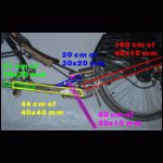
5. Middle Part:
- two pieces of rear axles with nuts (or two M8 bolts)
- two 37 mm long pieces of seat stay
- one front axle with nuts
- one rubber block
- another rear axle with nuts for the suspension pivot
- one steel crank
- 19 cm of 30x20x1.5 rectangular tubing
- 44 cm of 40x40x1.5 square tubing
- one steel front wheel hub
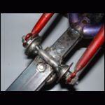
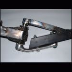
To get the functionality of the suspension, just meditate some minutes over the next picture. The suspension is simple but efficient. It can be adjusted to the system weight by preloading the rubber block more or less.
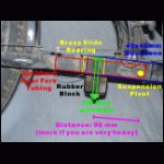
5a.
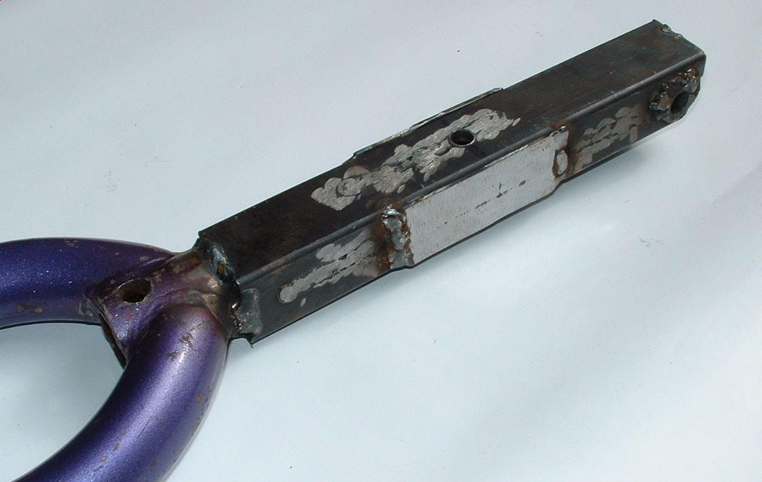
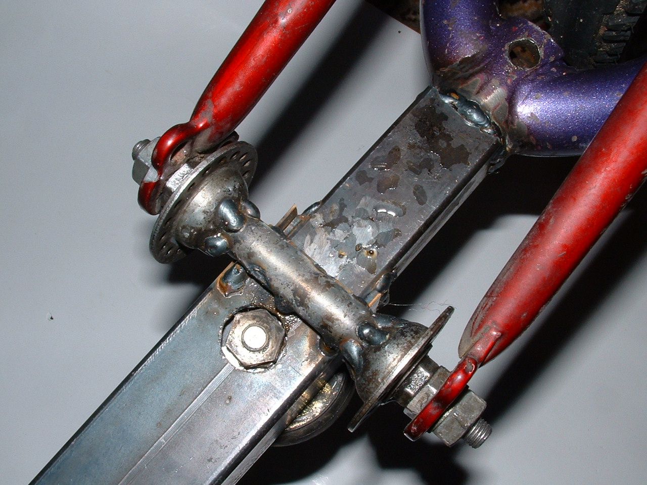
Drill a vertical hole in the 40x40 tube, about 30 mm from the rear edge. The upper side of the hole should be 20 mm in diameter, so that the nuts of the front wheel axle can fit through. The lower hole is just small enough for the axle itself. Then drill a horizontal hole 90 mm from the first hole, big enough for a rear axle. This hole is 3.5 mm below the middle of the 40x40 tube. Enforce the outer sides of this hole with washers, welded onto the tube. This will be the pivot of the suspension.
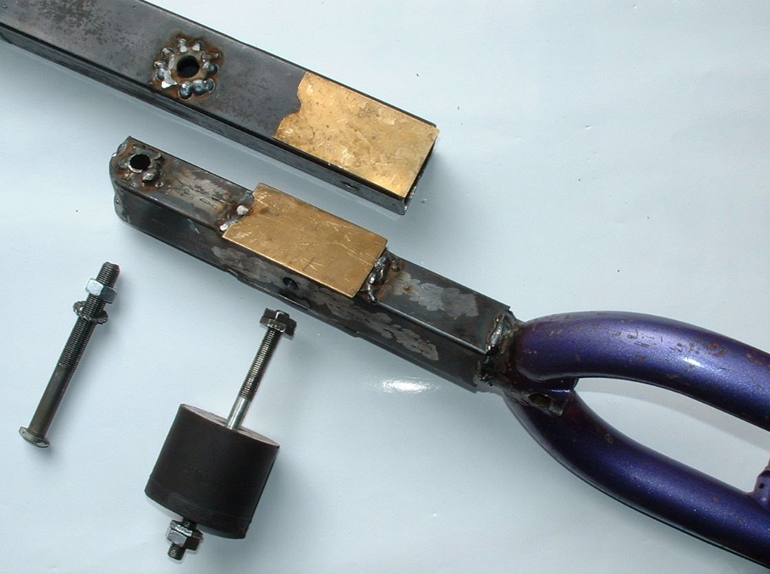
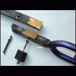
Now you have everything ready to assemble the whole suspension. On the next picture all parts are shown. The lower brass plate is already in position, the upper one just lies on the 40x40 to demonstrate its location inside. If your rubber block has no integrated steel plates, you will have to cut them out of 4 mm steel. If you cannot get a rubber block it can be replaced by a stack of cut wheel tube rings.
5b.
The upper part of the middle frame consists of a steel crank and the 30x20 tubing. Simply cut the crank at about 8 cm , sand away the chromium layer and weld it into the tube. The tube has two incisions. If the crank does not fit exactly, fill out the spaces with plates of steel. Make sure that the crank is in line with the tube.
If you cannot find a steel crank, and only have alloy ones, then do not cut it, but insert the whole length into the tube, drill two vertical holes through both pieces and push through two bolts. One of the bolts can be used to hold the seat in place.
5c.
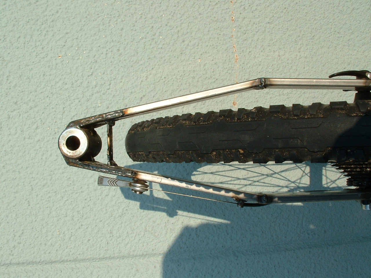
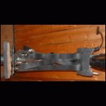
At last weld a steel FW hub to the rear end of the 40x40. (CORRECTION: better weld the hub close to the suspension pivot, as this will increase seat stability). The hub will be part of the hammock seat later. Notice that the cups of the hub are welded to the center part. Be sure that the hub is in line with the rear wheel. To control this you can mount a 28" fork for better adjustment.
6. Assembly:
Now it is time to assemble all frame parts and to connect them.
6a.
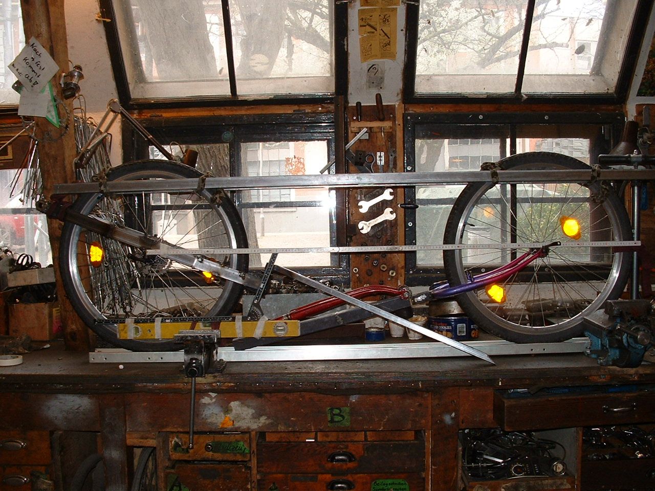
Mount the upper crank with the 30x20 tube on the BBS. Insert both wheels and put them vertically on a plane and horizontal desk. Adjust the desired steering angle (around 65°) and wheelbase (129 cm). Be sure that both wheels are perfectly in line. Two long rectangular tubes, holding both wheels in place will help you with that. Now cut the 30x20 and the 40x40 so that the 30x20 can be welded onto the upper side of the 40x40 and that the front edge of the 40x40 does not touch the BBS.
Before welding, check again all parameters. After welding, the geometry is fixed and you should take a break.
If you invest some time and build a frame jig, the process of lining everything up is greatly simplified.
6b.
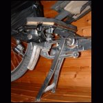
Now comes the funny part. Place the alloy crank on the BBS axle and determine the angle for bending it, so that the crank arm comes parallely to the 40x40. Unmount the crank, clamp it in a vice and heat the area where it should bend with an acetylene/oxygen or propane/oxygen torch. When the temperature is close to the annealing point, you should be able to draw a black line on the surface with a piece of wood. Now the alloy has the consistence of chewing gum and you can bend it without force. Let it cool down slowly and mount it on the BBS again to check the angle.
There have been discussions if this method of bending alloy is save. It never broke during the last 18.000 km and I do not expect problems, but if you want to be on the safer side, take a steel crank instead, slice it and weld it in the correct angle.
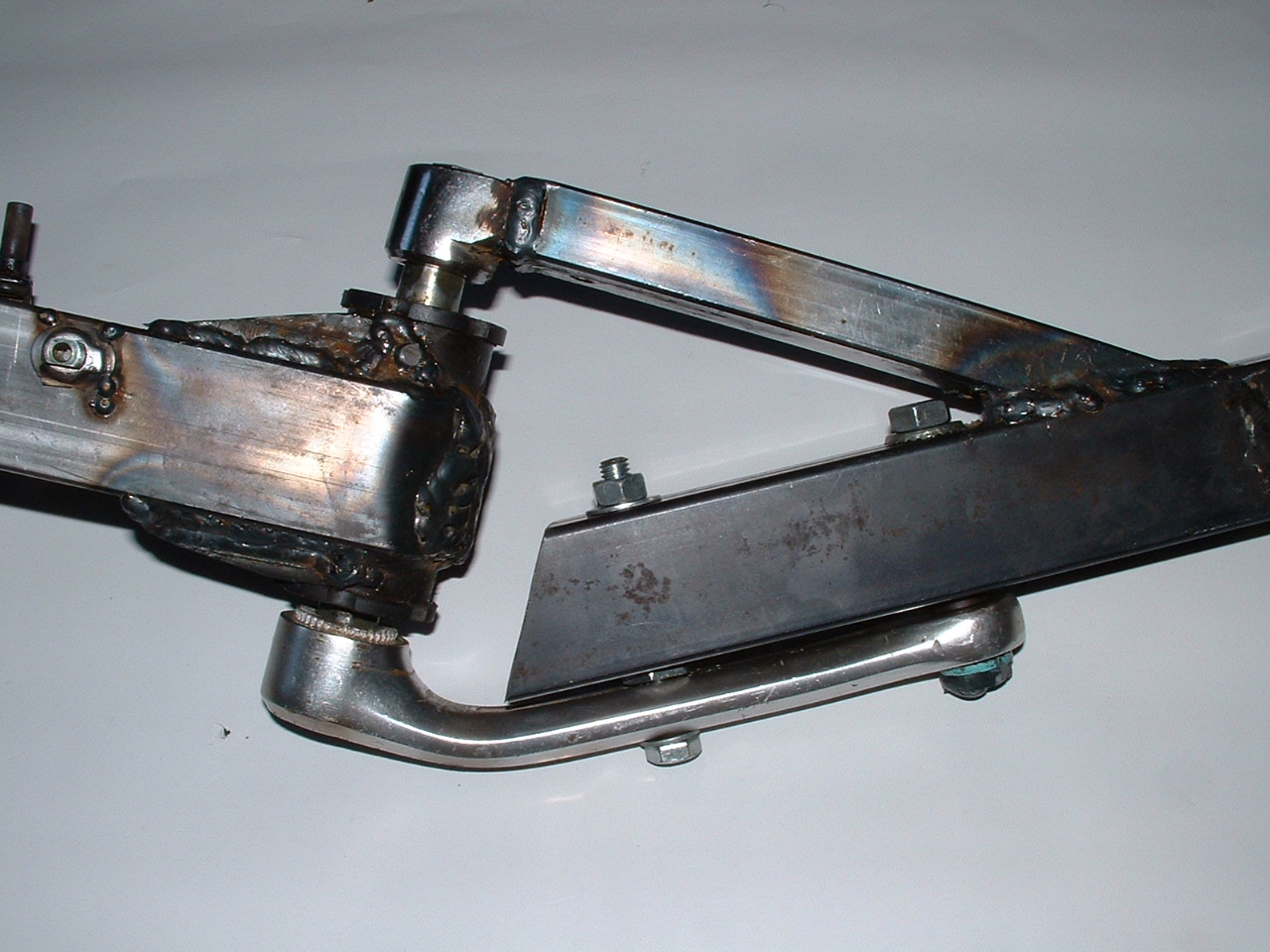
6c.
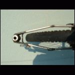
Drill two holes through both the bent alloy crank and the 40x40 tube, big enough for the RW axle or M8 bolts. Reinforce the tube with the seat stay pieces and insert the bolts. If there is some space left between the crank and the 40x40, fill it out with washers. Do not bent the crank with the bolts.
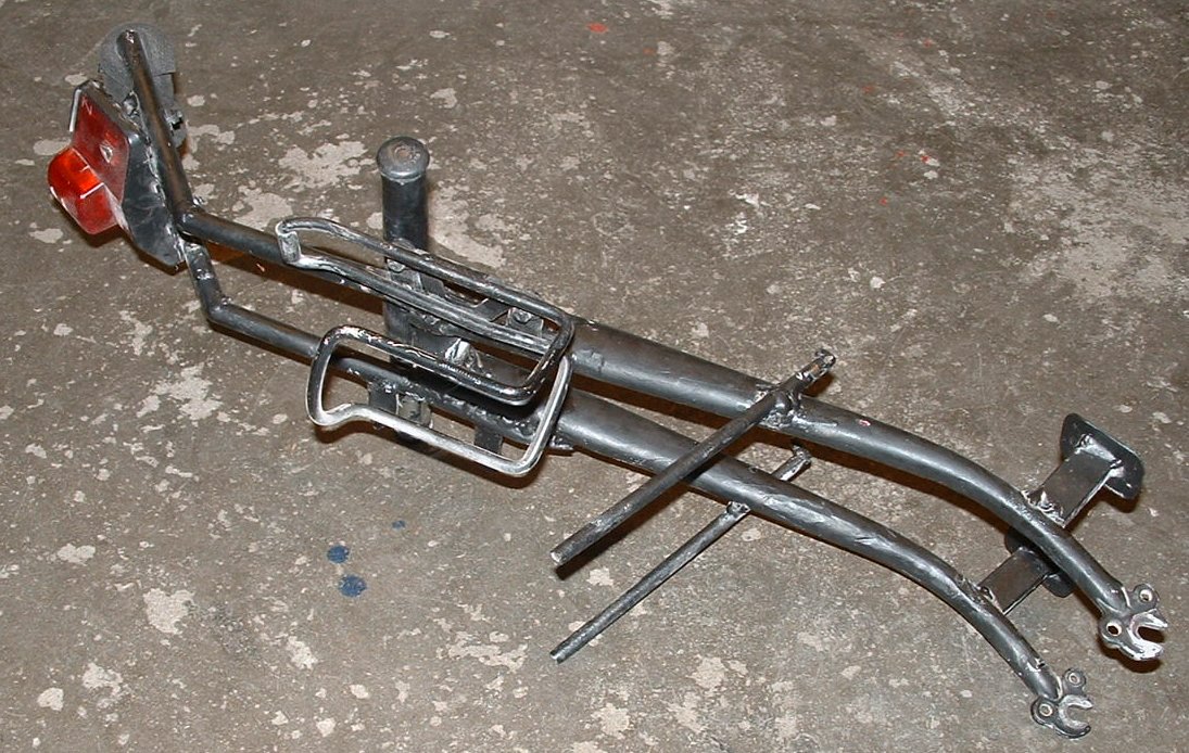
In the end it should look like the following picture.
7. Stand:
- 100 cm of 20x10x1.5 rectangular tubing
- one M8 bolt with nuts
- 15 cm of 40x10x1.5 tubing
It might sound strange to you that the stand is an important part of the building process. In case of the Python it is.
The kick-stand of the Python has 3 functions. First its original function as a stand. Second, when down, it blocks the front frame from moving, which is very important for the handling, e.g. carrying. And third it allows the rider to sit on the bike, pedaling and checking the gears, unmounting the wheels and do maintenance.
The stand is stable enough to carry the riders weight.
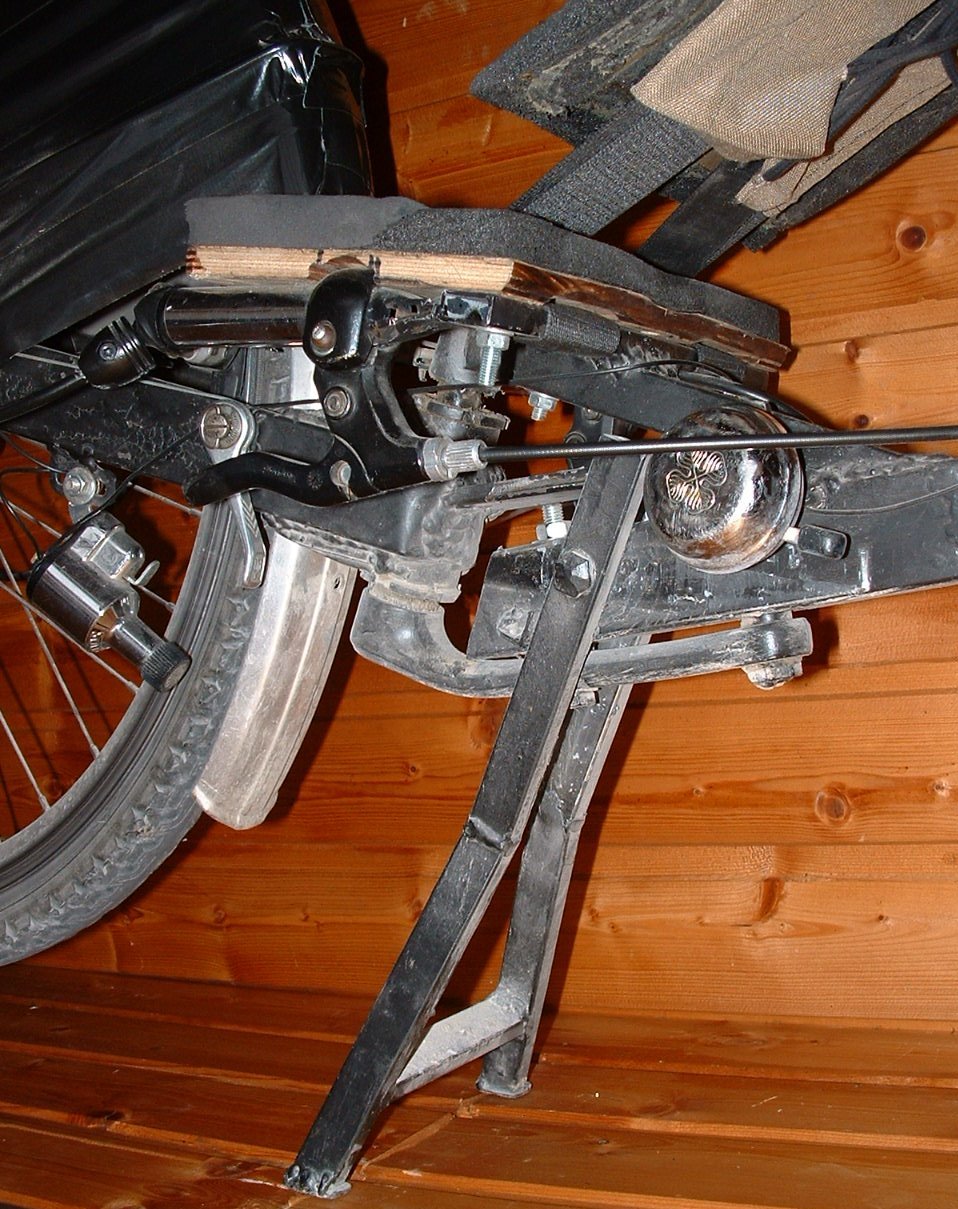
7a.
I hope that the picture is self explaining. First built the stand and assemble it, then weld the steering stop 40x10 tube to the steering BB shell so that the front part is perfectly in line with the rear part of the frame when the stand is down.
8. Seat:
- 3.2 m of safety belt
- one buckle
- one 20" fork
- one straight MTB steel handlebar
- one 28x20x1 cm plate of plywood
- one 25x15x1 cm plate of plywood
- 25 cm of 20x10x1.5 rectangular tubing
- some foam material
- three M5 bolts with round head
Of course you can mount any seat you like on the Python frame. I prefer a semi-hammock seat, because it is foldable, provides rain protection and is a stable support for bottle holder and pannier rack. Adjustment of the seat back angle is very easy.
8a.
The smaller plate is for the seat. Drill two holes at the outer ends of the 20x10 tube and fasten the plate with two M5 bolts at the rear edge to the tube. Place the plate with the tube on the upper crank/tube so that the front edge of the plate has 5 mm space to the front fender. Then weld the 20x10 tube onto the upper crank/tube. Drill a third hole through the plate and the crank/tube for the third M5 bolt.
8b.
Now remove the seat plate and cut off the outer parts of the handlebar, so that the middle part is as long as the seat back plate (28 cm). The ends of the two outer parts are pressed flat and welded to the outer ends of the 20x10 tube so that they are below the seat plate. With these two handlebar pieces you have holders for your brake levers.
8c.
Back to the seat plate. Make two incisions about 1 cm front of the 20x10 tube. The incisions should be as wide as the seat belt and its outer ends are given by the inner edges of the handlebar pieces. Cut out the front edge of the plate so that the front fender does not collide with the plate when making turns. About 45 deg to the left and right should be possible.
8d.
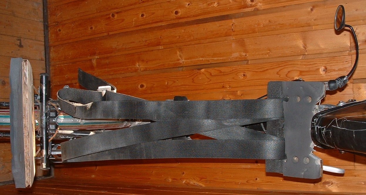
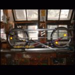
Cut of the steering tube part of the 20" fork and weld the handlebar onto it. Place the fork on the hub that is welded onto the 40x40 tube and check if the handlebar is absolutely 90 deg to the frame. Lead the safety belt around the handlebar and the seat plate as shown in the next picture and fasten it with the buckle or simply make a knot.
The seat back fork has several functions.
- holding the seat belt and the seat back plywood plate
- rear light holder, head rest and pushing handle
- bottle holder
- pannier rack for Ortlieb frontroller
The two thingies below the pannier rack are for protecting the panniers from luggage stored directly under the seat.
The seat is satisfying stable, foldable and quite comfortable, though not as comfy as a commercial seat, I suppose.
The seat angle can be adjusted very easily, by changing the seat belt length with the buckle.
8e.
Drill 4 holes through the seat back plate and bind it with a rope to the handlebar. Glue the foam material on both plates and adjust the seat angle by playing with the length of the seat belt. If you want fill out the gap between both seat plates with a movable foam plate for better back support.